Driving DotStar RGB LEDs
The DotStar (APA102) is an RGB LED in a small 5050 package that incorporates a microcontroller so you control the colour and brightness using a two-wire SPI signal. You can also daisy-chain a virtually unlimited number of them together, with individual control over the colour and brightness of each LED:
You can buy them in strips, or as individual LEDs. I chose the individual LEDs, available from Adafruit [1] or from The Pi Hut in the UK [2].
You could carefully solder 6 wires to each 5050 package, but I mounted them on breakout boards available from Adafruit [3].
Connecting the DotStar
If you're using an Arduino Uno or ATmega328 connect the pins as follows:
- Arduino Pin 11 (MOSI) to DI.
- Arduino pin 13 (SCK) to CI.
- GND to GND.
- 5V to VCC.
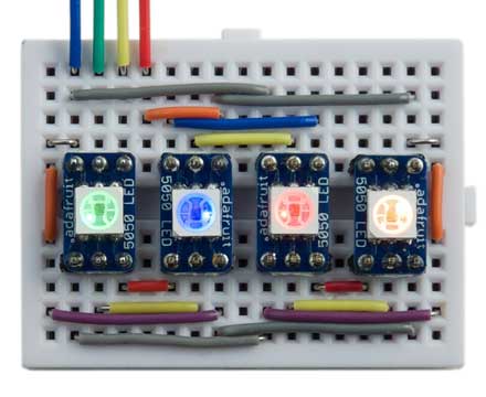
Here's the circuit I used with four DotStar devices:
Controlling the DotStar
The DotStar is programmed using a two-wire SPI signal (ignoring the enable and MISO signals). The data consists of:
- A start frame of 32 '0' bits.
- A 32-bit frame for each LED, specifying the brightness and colour.
- An end frame of 32 '1' bits.
The 32-bit frame for each LED consists of:
- Three '1' bits.
- Five bits specifying the brightness, MSB first.
- Eight bits specifying the blue component, MSB first.
- Eight bits specifying the green component, MSB first.
- Eight bits specifying the red component, MSB first.
Because you can specify the brightness independently of the individual R, G, and B components, the overall resolution is actually 13 bits.
The uLisp program
Here's the definition of a uLisp program display, suitable for an Arduino Uno upwards, to control a chain of LEDs:
(defun display (lst)
  (with-spi (str 10)
       (dotimes (x 4) (write-byte #x00 str))
       (mapc
        (lambda (col)
          (write-byte (logior (first col) #xE0) str)
          (mapc
           (lambda (b) (write-byte b str))
           (cdr col)))
        lst)
       (dotimes (x 4) (write-byte #xFF str))))
It specifies the enable signal as pin 10, although this isn't actually used.
To use it, call it with a list of the following values for each LED:
(brightness blue green red)
where brightness is a number from 0 to 31, and the other numbers are values from 0 to 255.
For example, to set a row of four LEDs to blue, green, red, orange, each with a brightness of 1/32, evaluate:
(display '((1 255 0 0) (1 0 255 0) (1 0 0 255) (1 255 0 255)))
Using uLisp it's fairly simple to set up changing patterns or sequences of colours on a row of these LEDs.
- ^ DotStar 5050 RGB LED with Integrated Driver Chip on Adafruit.
- ^ Adafruit DotStar 5050 RGB LED with Integrated Driver Chip on The Pi Hut.
- ^ 5050 LED breakout PCB on Adafruit.