BBC Micro:bit and Calliope Mini
The BBC Micro:bit is a low-cost controller board half the size of a credit card, pioneered by the BBC in the UK. The latest version is Version 2.
The Calliope mini is a single-board computer inspired by the BBC Micro:bit, and developed for use in German primary schools.
Boards
Common features
Installing uLisp on the BBC Micro:bit or Calliope mini
You can install the ARM Version uLisp using the Arduino IDE as follows:
- Download the ARM version of uLisp from the downloads page: Download and install uLisp.
- In the Arduino IDE open the Preferences dialog box, and add the following URL to Additional Board Manager URLs:
https://sandeepmistry.github.io/arduino-nRF5/package_nRF5_boards_index.json
- Open the Boards Manager… from the Board item on the Tools menu, search for nRF5, and install Nordic Semiconductor nRF5 Boards by Sandeep Mistry.
- Connect the BBC Micro:bit/Calliope mini to your computer using a USB cable.
- From the Board menu select BBC micro:bit for version 1.3 or 1.5, BBC micro:bit V2 for version 2, or Calliope mini for the Calliope mini.
- Set Softdevice to None, and set Port to the USB port.
You should now be able to upload uLisp to the board.
To use the full 32 kbytes of RAM available on the Calliope mini see Using the full 32 Kbytes of RAM.
Follow the instructions in Using uLisp to interact with uLisp on the board.
Updating the serial buffer
As of uLisp Version 3.6 there is no longer a problem pasting large Lisp programs in via the Serial Monitor, so there is no need to change the serial buffer size from the default.
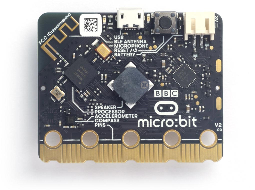
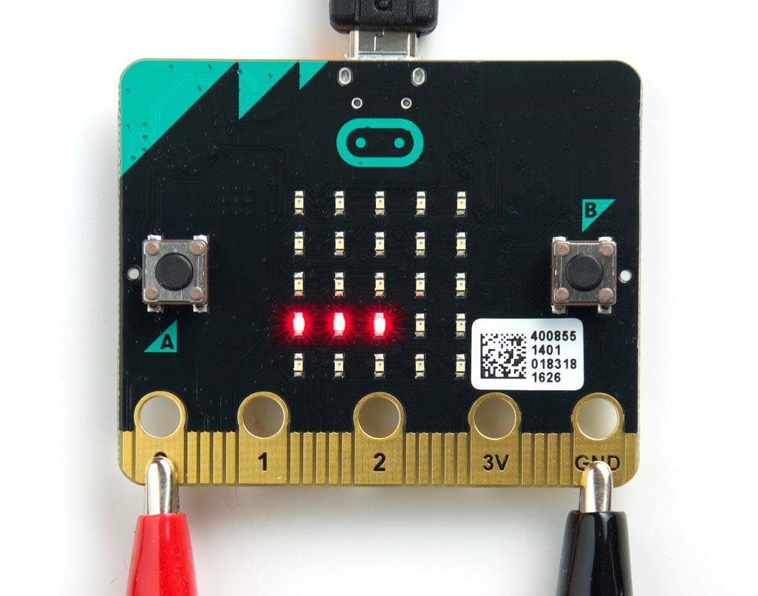
BBC Micro:bit V2
The BBC Micro:bit V2 is based on a Nordic Semiconductor nRF52833 ARM Cortex-M4 microcontroller, running at 64 MHz, and it provides 512 Kbytes of flash program memory, and 128 Kbytes of RAM:
It supports the ARM Assembler; see ARM assembler overview.
BBC Micro:bit V2.00 and V2.20 are functionally identical, and differ only in a component on the board to solve supply shortages.
Pin connections
The BBC Micro:bit provides 19 digital input/output pins, 6 analogue inputs, and 19 analogue outputs. They are accessible from the edge connector as follows:
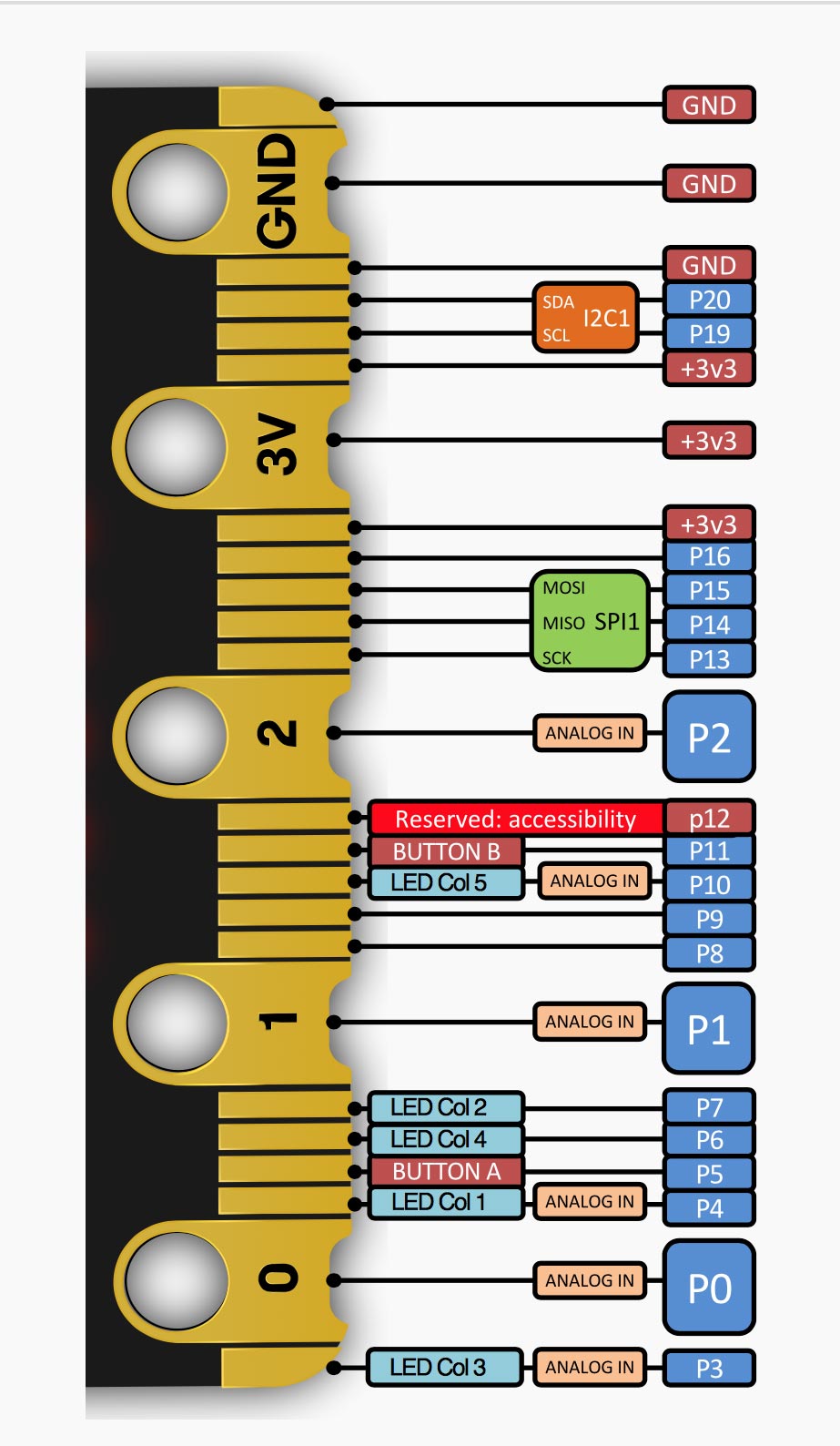
For more detailed information about the edge connector see the microbit.org site [1]. The board also includes two pushbuttons and a matrix of 5 x 5 multiplexed LEDs. See Example programs below for examples of using these from uLisp.
Buttons
The reverse side of the BBC Micro:bit provides two pushbuttons on pins 5 and 11. You can read these with the following program:
(defun buttons ()
  (pinmode 5 :input)
  (pinmode 11 :input)
  (loop
   (print
    (list (digitalread 5) (digitalread 11)))
   (delay 1000)))
Run it by typing:
(buttons)
LEDs
The reverse of the BBC Micro:bit also provides a matrix of 5 x 5 LEDs. In the BBC Micro:bit Version 2 these are connected in a more logical matrix of five rows and five columns, so to light any individual LED you need to take the column low and the row high corresponding to that LED.
The following table shows the pin numbers for the rows and columns:
| 4 | 7 | 3 | 6 | 10 | |
| 21 | • | • | • | • | • |
| 22 | • | • | • | • | • |
| 23 | • | • | • | • | • |
| 24 | • | • | • | • | • |
| 25 | • | • | • | • | • |
This program flashes the LED at (row, column):
(defun blink (row column)
  (let (x)
    (pinmode row :output)
    (pinmode column :output)
    (digitalwrite row t)
    (loop
     (digitalwrite column x)
     (delay 1000)
     (setq x (not x)))))
For example, to flash the centre LED run:
(blink 23 3)
Analogue inputs
The BBC Micro:bit Version 2 provides seven 10-bit analogue inputs, 0 (A0) to 4 (A4), 10 (A5), and 29 (A6).
Three of these are available on the edge connector pins labelled 0, 1, and 2. The following example program reads the analogue input on pin 0 and displays the value as a bar of LEDs, using the fourth row of LEDs on the matrix.
Here's the program:
(defun meter ()
  (let ((col '(4 7 3 6 10))
        (row 24))
    (pinmode row :output)
    (digitalwrite row t)
    (mapc (lambda (x) (pinmode x :output)) col)
    (loop
     (dotimes (n 5)
       (digitalwrite
        (nth n col)
        (<
         (analogread 0)
         (* (1+ n) 170)))))))
To run it evaluate:
(meter)
If you touch pin 0 on the edge connector you'll see the bar flash from the voltage on your finger. Connect a voltage of up to 3.3V to pin 0 to display a bar of LEDs in proportion to the voltage.
Analogue outputs
Any pin can also be used as an 8-bit analogue output, so you can pulsate the LED at (row, column) slowly on and off with the following program:
(defun pulse (row column)
  (let (down)
    (pinmode row :output)
    (digitalwrite row t)
    (loop
     (dotimes (x 256)
       (delay 5)
       (analogwrite column (if down (- 255 x) x)))
     (setq down (not down)))))
Run it by typing:
(pulse 23 3)
Exit from any program by entering ~.
Serial
The BBC Micro:bit V2 has one serial port on pin numbers 0 (RX) and 1 (TX).
SPI
The BBC Micro:bit V2 has one SPI port on pin numbers 12 (MISO), 11 (MOSI), and 13 (SCK). The clock can be between 125 kHz and 8 MHz.
I2C
The BBC Micro:bit V2 provides two I2C ports. Port 0 is connected to the edge connector, and is on pins 20 (SDA) and 16 (SCL). Port 1 provides access to the internal I2C devices, and is on pins 30 (SDA) and 31 (SCL).
To access the internal I2C devices give the with-i2c command with the port as a second parameter. For example, to scan port 1 give:
(defun scn ()
  (dotimes (p 127)
    (with-i2c (str 1 p)
      (when str (print p)))))
This displays the following device addresses:
| Address | Device |
| 25 (#x19) | LSM303AGR accelerometer |
| 30 (#x1E) | LSM303AGR magnetometer |
| 112-114 (#x70-#x72) | NXP KL27Z interface processor |
LSM303AGR accelerometer/magnetometer
The LSM303AGR sensor contains both an accelerometer and a magnetometer. For details of using it see:
LSM303D Accelerometer Magnetometer
BBC Micro:bit
The original BBC Micro:bit V1.30 is based on a Nordic Semiconductor nRF51822-QFAA ARM Cortex-M0 microcontroller, running at 16 MHz, and it provides 256 Kbytes of flash program memory and 16 Kbytes of RAM:
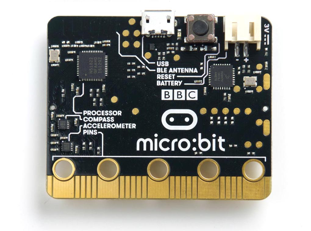
A later update, BBC Micro:bit V1.50, is similar except that it has a single LSM303AGR sensor which contains both an accelerometer and a magnetometer.
Pin connections
The BBC Micro:bit provides 19 digital input/output pins, 6 analogue inputs, and 19 analogue outputs. They are accessible from the edge connector as follows:
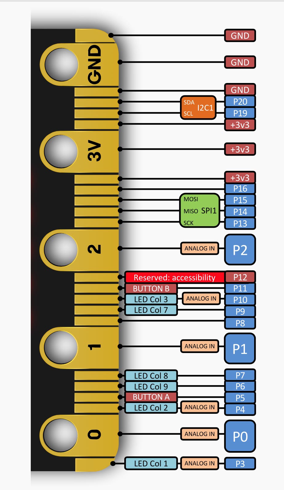
The board also includes two pushbuttons and a matrix of 5 x 5 multiplexed LEDs. See Example programs below for examples of using these from uLisp.
Buttons
The reverse side of the BBC Micro:bit provides two pushbuttons on pins 5 and 11. You can read these with the following program:
(defun buttons ()
  (pinmode 5 :input)
  (pinmode 11 :input)
  (loop
   (print
    (list (digitalread 5) (digitalread 11)))
   (delay 1000)))
Run it by typing:
(buttons)
LEDs
The reverse of the BBC Micro:bit also provides a matrix of 5 x 5 LEDs. They are connected in a totally illogical arrangement of nine columns and three rows, and to light any individual LED you need to take the column low and the row high corresponding to that LED.
The following table shows the (row, column) for each LED:
| (26, 3) | (27, 23) | (26, 4) | (27, 24) | (26, 10) |
| (28, 23) | (28, 24) | (28, 25) | (28, 9) | (28, 7) |
| (27, 4) | (26, 6) | (27, 10) | (28, 6) | (27, 3) |
| (26, 7) | (26, 9) | (26, 25) | (26, 24) | (26, 23) |
| (28, 10) | (27, 9) | (28, 3) | (27, 25) | (28, 4) |
This program flashes the LED at (row, column):
(defun blink (row column)
  (let (x)
    (pinmode row :output)
    (pinmode column :output)
    (digitalwrite row t)
    (loop
     (digitalwrite column x)
     (delay 1000)
     (setq x (not x)))))
For example, to flash the centre LED run:
(blink 27 10)
Analogue inputs
The BBC Micro:bit provides six 10-bit analogue inputs, on pins 0 (A0) to 4 (A4) and 10 (A5).
Three of these are available on the edge connector pins labelled 0, 1, and 2. The following example program reads the analogue input on pin 0 and displays the value as a bar of LEDs, using the fourth row of LEDs on the matrix:
The program takes advantage of the fact that this row of LEDs share the same row number. Here's the program:
(defun meter ()
  (let ((col '(7 9 25 24 23))
        (row 26))
    (pinmode row :output)
    (digitalwrite row t)
    (mapc (lambda (x) (pinmode x :output)) col)
    (loop
     (dotimes (n 5)
       (digitalwrite
        (nth n col)
        (<
         (analogread 0)
         (* (1+ n) 170)))))))
To run it evaluate:
(meter)
If you touch pin 0 on the edge connector you'll see the bar flash from the voltage on your finger. Connect a voltage of up to 3.3V to pin 0 to display a bar of LEDs in proportion to the voltage.
Analogue outputs
Any pin can also be used as an 8-bit analogue output, so you can pulsate the centre LED slowly on and off with the program:
(defun pulse (row column)
  (let (down)
    (pinmode row :output)
    (digitalwrite row t)
    (loop
     (dotimes (x 256)
       (delay 5)
       (analogwrite column (if down (- 255 x) x)))
     (setq down (not down)))))
Run it by typing:
(pulse 27 10)
Exit from any program by entering ~.
Serial
The BBC Micro:bit has one serial port on pin numbers 21 (RX) and 22 (TX).
SPI
The BBC Micro:bit has one SPI port on pin numbers 14 (MISO), 15 (MOSI), and 13 (SCK).
I2C
The BBC Micro:bit has one I2C port on pin numbers 20 (SDA) and 19 (SCL).
MMA8653FC 3-axis, 10-bit digital accelerometer
The Micro:bit includes an MMA8653FC accelerometer is on I2C address 29 (#x1D).
MAG3110 3-axis magnetometer
The Micro:bit includes an MAG3110 magnetometer is on I2C address 14 (0x0E). For details of using it see:
LSM303AGR accelerometer/magnetometer
Newer versions of the Micro:bit have a single LSM303AGR sensor which contains both an accelerometer and a magnetometer. For details of using it see:
LSM303D Accelerometer Magnetometer
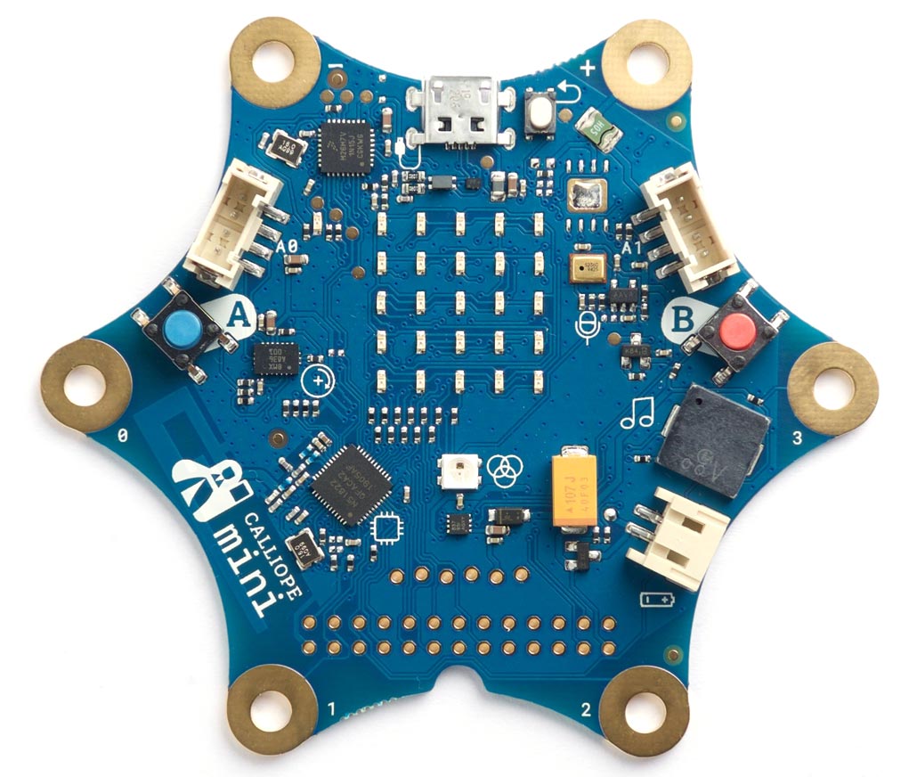
Calliope mini
The Calliope mini [2] is a single-board computer developed for use in German primary schools. It is inspired by the BBC Micro:bit, and shares some of its features.
Like the BBC Micro:bit it is based on the Nordic Semiconductor nRF51822 ARM Cortex-M0 microcontroller running at 16 MHz and with 256 Kbytes of flash program memory. The boards produced from 2019 onwards use the nRF51822-QFAC version with 32 Kbytes of RAM, twice as much as the BBC Micro:bit:
It's available from Adafruit [3], or from Amazon in the UK [4].
Like the BBC Micro:bit it includes a 5x5 LED matrix display, two push buttons, banana plug/crocodile clip connections, and a JST battery connector. It also features a MEMS microphone, piezo speaker, DC Motor Driver (TI DRV8837), two Grove connectors (I2C + serial/analog), and a space for an optional DataFlash chip.
It is named after Kalliope, a daughter of Zeus and the muse who presides over eloquence, science, and epic poetry.
Using the full 32 Kbytes of RAM
The Arduino core assumes that the Calliope mini has 16 Kbytes of RAM. To take advantage of the full 32 Kbytes you need to make the following changes before uploading uLisp:
- Locate the boards.txt file at:
/Users/david/Library/Arduino15/packages/sandeepmistry/hardware/nRF5/0.6.0/boards.txt
replacing David by the name of your user folder, and 0.6.0 by the version of Sandeepmistry you have installed.
- Edit the following three entries as shown, changing "xxaa" to "xxac" in each case:
CalliopeMini.build.ldscript=nrf51_xxac.ld
CalliopeMini.menu.softdevice.s110.build.ldscript=armgcc_s110_nrf51822_xxac.ld
CalliopeMini.menu.softdevice.s130.build.ldscript=armgcc_s130_nrf51822_xxac.ld
- Change the #define in the ARDUINO_CALLIOPE_MINI section in the ulisp-arm.ino file as follows, to increase the workspace to use this extra space:
#define WORKSPACESIZE 3328 /* Objects (8*bytes) */
Pin connections
The Calliope mini has 6 pads which can take crocodile clips or banana plugs.
The board also includes two pushbuttons and a matrix of 5 x 5 multiplexed LEDs. See Example programs below for examples of using these from uLisp.
Buttons
The Calliope mini provides two pushbuttons on pins 20 (A) and 22 (B). You can read these with the following program:
(defun buttons ()
  (pinmode 20 nil)
  (pinmode 22 nil)
  (loop
   (print
    (list (digitalread 20) (digitalread 22)))
   (delay 1000)))
Run it by typing:
(buttons)
LEDs
The Calliope mini provides a matrix of 5 x 5 LEDs. They are connected in an illogical arrangement of nine rows and three columns, and to light any individual LED you need to take the row low and the column high corresponding to that LED.
The following table shows the (row, column) for each LED:
| (4, 13) | (7, 14) | (5, 13) | (8, 14) | (6, 13) |
| (7, 15) | (8, 15) | (9, 15) | (10, 15) | (11, 15) |
| (5, 14) | (12, 13) | (6, 14) | (12, 15) | (4, 14) |
| (11, 13) | (10, 13) | (9, 13) | (8, 13) | (7, 13) |
| (6, 15) | (10, 14) | (4, 15) | (9, 14) | (5, 15) |
This program flashes the LED at (row, column):
(defun b (row col)
  (let ((x t))
    (pinmode row t)
    (pinmode col t)
    (digitalwrite row nil)
    (loop
     (digitalwrite col x)
     (delay 1000)
     (setq x (not x)))))
For example, to flash the centre LED run:
(b 6 14)
Analogue inputs
The Calliope Mini provides eight 10-bit analogue inputs, on pins 1 (A1), 2 (A2), 4 (A3) to 6 (A5), 16 (A6), and 17 (A7). Two of them are available on the edge connector pads labelled 1 and 2. Pin 28 (A0) is connected to the microphone.
The following example program reads the analogue input on pin 1 and displays the value as a bar of LEDs, using the fourth row of LEDs on the matrix. The program takes advantage of the fact that this row of LEDs share the same column number and have consecutive row numbers. Here's the program:
(defun meter ()
  (let ((row 7) (col 15))
    (pinmode col t)
    (digitalwrite col t)
    (dotimes (i 5) (pinmode (+ row i) t))
    (loop
     (dotimes (i 5)
       (digitalwrite
        (+ row i)
        (<
         (analogread 1)
         (* (1+ i) 170)))))))
To run it evaluate:
(meter)
If you touch pad 1 on the edge connector you'll see the bar flash from the voltage on your finger. Connect a voltage of up to 3.3V to pad 1 to display a bar of LEDs in proportion to the voltage.
Analogue outputs
Any pin can also be used as an 8-bit analogue output, so you can pulsate the centre LED slowly on and off with the program:
(defun pulse ()
  (let (down)
    (pinmode 6 t)
    (digitalwrite 6 nil)
    (loop
     (dotimes (x 256)
       (delay 5)
       (analogwrite 14 (if down (- 255 x) x)))
     (setq down (not down)))))
Run it by typing:
(pulse)
Exit from any program by entering ~.
Serial
The Calliope Mini has one serial port on pin numbers 30 (RX) and 29 (TX).
SPI
The Calliope Mini has one SPI port on pin numbers 16 (MISO), 17 (MOSI), and 22 (SCK).
I2C
The Calliope Mini has one I2C port on pin numbers 18 (SDA) and 19 (SCL).
DataFlash capability
Interestingly the Calliope mini circuit board has a space for a 8-pin surface-mount DataFlash chip, type M45PE80 (8 Mbyte) or M45PE16 (16 Mbyte). It's possible this could be used to add the ability to save and load uLisp images to the board.
- ^ Edge Connector and Pinout on microbit.org.
- ^ Calliope mini website.
- ^ Calliope mini on Adafruit.
- ^ Calliope mini on Amazon.