ARM NeoPixel driver using assembler
This page describes a NeoPixel driver, written in ARM machine code using the uLisp assembler, that will control a single NeoPixel LED, or a strip of an unlimited number of NeoPixels, on a variety of ARM-based boards including ATSAMD21, ATSAMD51, nRF52840, RP2040, and RP2350.
The routine can be calibrated for any processor, so it doesn't rely on knowing the instruction timings or processor clock rate for the board you are using.
1st June 2025: Added more explanation about how the wave example works.
31st May 2025: This page has been updated, with many improvements and support for many additional boards.
Introduction
NeoPixel is the name given by Adafruit to the WS2812, a chainable RGB LED invented in 2013 by the Shenzhen-based company Worldsemi. You can power them with 5V or 3.3V, and chain them together, tying the data-out pin of one NeoPixel to the data-in of the next one in the chain. There's an excellent overview of NeoPixels on the Adafruit site [1].
You can get single NeoPixels in a variety of shapes and sizes: Through-hole: 8mm [2], and 5mm [3]; SMD: 5050 [4], 3535 [5], 2427 [6], and 1515 [7]. You can also get them already mounted in almost any configuration, including strips, discs, and matrixes.
The NeoPixel protocol
NeoPixels use a non-standard protocol consisting of a serial stream of pulses, and the width of each pulse determines whether it is a '0' or a '1'. However the pulses are very short; a zero is defined as having a maximum width of 500ns, which is just 8 cycles on a 16 MHz CPU. Most NeoPixel libraries therefore use assembler routines tailored to each processor, at least for the low-level pulse generation.
The datasheet [8] specifies these timings as the ideal timings for the zero and one bits, and the gaps after each bit:
![]()
All the timings have a tolerance of ±150 ns.
In addition the datasheet specifies that the data line should remain low for at least 50 µs between each stream of data; this resets the NeoPixels, so subsequent data is interpreted as starting from the beginning of the chain again.
An analysis of WS2812 by user cpldcpu found that the reset time is actually 9 µs, and that the only critical timing is the duration of the T0H pulse, which should be between 62.5 ns and 500 ns [9]. All the other timings can be extended without breaking the protocol.
The colour for each NeoPixel display is specified by a stream of 24 bits:
![]()
Avoiding flicker
The average length of a bit is 1125 ns, so the time taken to configure one NeoPixel is about 30 µs plus a reset time of 9 µs; call it 40 µs. Our persistence of vision sees lights flashing at at least 100 Hz as being steady, which corresponds to once every 10000 µs. The maximum length of NeoPixel strip that can be animated without flicker is therefore 250 NeoPixels.
You can get around this limit by driving multiple shorter strips from separate output pins.
Installing the neopixel routine
To install the neopixel routine proceed as follows:
- Load the latest version of the ARM assembler from here: ARM assembler in uLisp.
- Load the board-specific settings for the board you are using; see Board-specific settings below.
- Install the pulse macro and neopixel assembler program: NeoPixel assembler program.
- Save the neopixel routine by doing:
(save-image)
You will then be able to use the neopixel routine at a later time simply by executing (load-image), without needing to assemble the program again. You will just need to define the NeoPixel pin as an output by doing:
(pinmode *arduino-pin* :output)
Assembler routine - neopixel
The assembler routine, neopixel, takes two parameters: the pin number connected to the NeoPixels, and a list of the colour values for each LED in the strip:
(neopixel pin-bit colours)
The pin is the bit position in the output port, defined as *pin-bit* in the board settings below.
The parameter colours is a list of hexadecimal colour values in the format:
#xGGRRBB
specifying the green, red, and blue components of the colour. Each pair of digits can be between #x00 and #xff, where #xff corresponds to the maximum brightness for that colour. A value of #xff is very bright, so the following examples use smaller values.
For example, on a Neo Trinkey you can set the four neopixels to red, green, blue, and yellow with:
(neopixel 5 '(#x003f00 #x3f0000 #x00003f #x3f3f00))
If you just want to light up a single NeoPixel on a board, give one hexadecimal value in the list; for example:
(neopixel 5 '(#x070f00))
Here’s the neopixel assembler routine:
(defcode neopixel (pin lst)
  ($push '(lr r5 r4))
  ($ldr 'r4 port)
  ($mov 'r3 1)
  ($lsl 'r3 'r0)
  repeat
  ($cmp 'r1 0)
  ($beq finished)
  ($ldr 'r0 '(r1 0))
  ($ldr 'r0 '(r0 4))
  ($mov 'r2 1)
  ($lsl 'r2 23)
  nextbit
  ($tst 'r0 'r2)
  ($bne one)
  zero
  ($cpsid 3)
  ($str 'r3 '(r4 *outset*))
  (pulse 350)
  ($str 'r3 '(r4 *outclr*))
  (pulse 800)
  ($cpsie 3)
  ($b next)
  one
  ($str 'r3 '(r4 *outset*))
  (pulse 700)
  ($str 'r3 '(r4 *outclr*))
  (pulse 600)
  next
  ($lsr 'r2 1)
  ($bne nextbit)
  ($ldr 'r1 '(r1 4))
  ($b repeat)
  finished
  ($pop '(r4 r5 pc))
  port
  ($word *port-address*))
A pointer to the colours list is passed to the assembler routine in r0. For each integer in this list the bits are tested one at a time, starting with bit 23, and then the appropriate code at the labels zero or one is executed to generate a pulse with the appropriate timing.
$cpsid and $cpsie instructions are used to disable interrupts around the most time-critical part of the routine, which generates the ‘0’ pulse, to prevent them from possibly affecting the pulse timings.
Pulse macro
The neopixel assembler routine uses a pulse macro written in Lisp:
(defun pulse (ns)
  (let ((n (round ns *delay*)))
    (list
     ($mov 'r5 n)
     ($sub 'r5 1)
     ($bne (- *pc* 2)))))
This inserts a list of assembler instructions into the assembler program at the appropriate point to get a pulse of a specified delay in nanoseconds. They put the value of n into r5, and then repeatedly subtract 1 until it reaches zero. The loop is therefore executed n times.
The constant *delay* is a floating-point number specifying the time to execute one iteration of the pulse loop, in nanoseconds. For example, on a 48 MHz ATSAMD21 board it should be defined as:
(defvar *delay* 62.8)
I'll give the value of *delay* for several popular boards, but see the note at the end of the article about how to measure it on any arbitrary ARM board or clock rate.
Board-specific settings
In addition to needing the correct *delay* value, the neopixel assembler routine requires you to define the following Lisp global variables to give information about the board used to interface to the NeoPixel strip:
- The base address of the port used for the I/O pin, *port-address*.
- The offset of the port used to set a bit on the I/O pin, *outset-offset*.
- The offset of the port used to clear a bit on the I/O pin, *outclr-offset*.
- The bit position in those ports corresponding to the I/O pin used, *pin-bit*.
For example, for the ATSAMD21 these are:
(defvar *port-address* #x41004400)
(defvar *outset-offset* #x18)
(defvar *outclr-offset* #x14)
(defvar *pin-bit* 4)
See below for the values for popular boards.
In addition, you need to define the NeoPixel pin as an output before running the neopixel routine. This just needs to be done once, and the simplest way is to use the uLisp function pinmode:
(pinmode arduino-pin :output)
In some cases the arduino-pin is the same as the bit position in the port, but this is not always the case; see below.
The following sections give the details for specific boards. In each case the pulse macro and neopixel assembler routine are the same; you just need to define the globals for each board first before assembling it.
Adafruit Pixel Trinkey (ATSAMD21)
The Adafruit Pixel Trinkey is Adafruit's USB-A dongle sized board for driving NeoPixel and Dotstar displays, and with a single NeoPixel on the board:
![]()
Use these settings to control the on-board NeoPixel:
(defvar *delay* 62.8)
(defvar *port-address* #x41004400)
(defvar *outset* #x18)
(defvar *outclr* #x14)
(defvar *pin-bit* 1)
(defvar *pin* 1)
To run a NeoPixel strip from the Data pin on the terminal block change the definitions of *pin-bit* and *pin* to:
(defvar *pin-bit* 4)
(defvar *pin* 2)
Before running the neopixel routine execute this command to make the NeoPixel pin an output:
(pinmode *pin* :output)
Alternatively you can drive up a second NeoPixel strip from the Clock output on the terminal block with the following definitions:
(defvar *pin-bit* 5)
(defvar *pin* 3)
There is a resistor divider across the 5V VBUS signal and GND to allow you to read the voltage with the analogue input on pin 0. The following function returns the voltage:
(defun voltage () (/ (* (analogread 0) 6.6) 1024))
For example:
> (voltage)
5.05313
Adafruit Neo Trinkey (ATSAMD21)
The Adafruit Neo Trinkey is a good board to experiment with the neopixel routine. Despite its diminuitive size it includes four NeoPixels:
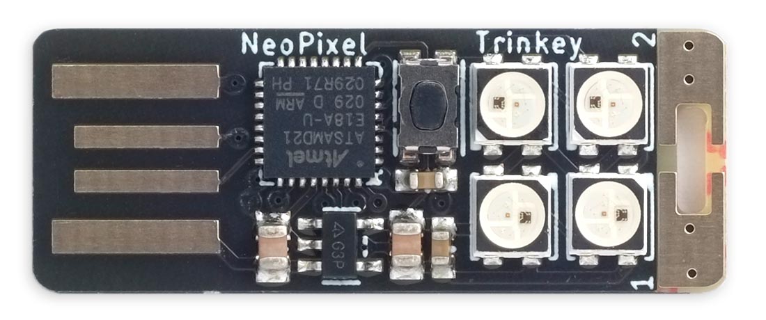
Upload uLisp using the Adafruit Pixel Trinkey M0 (SAMD21) board option.
To control the four on-board NeoPixels use these settings:
(defvar *delay* 62.8)
(defvar *port-address* #x41004400)
(defvar *outset* #x18)
(defvar *outclr* #x14)
(defvar *pin-bit* 5)
(defvar *pin* 3)
Before running the neopixel routine execute this command to make the NeoPixel pin an output:
(pinmode *pin* :output)
Here's a command that sets the NeoPixels to four different colours:
(neopixel *pin-bit* '(#x100000 #x001000 #x000010 #x100010))
Adafruit QT Py SAMD21 (ATSAMD21)
The Adafruit QT Py SAMD21 has a single NeoPixel on the board. Use the following settings:
(defvar *delay* 62.8)
(defvar *port-address* #x41004400)
(defvar *outset* #x18)
(defvar *outclr* #x14)
(defvar *pin-bit* 18)
(defvar *pin* 11)
Before running the neopixel routine execute this command to make the NeoPixel pin an output:
(pinmode *pin* :output)
The NeoPixel is powered by pin 12, so you need to make this an output too, and make it high, with:
(pinmode 12 :output)
(digitalwrite 12 :high)
To turn the NeoPixel blue:
(neopixel *pin-bit* '(#x000010))
Alternatively you can control an external string of NeoPixels by connecting them to one of the pins on the QT Py, as well as the GND and 5V connections. I suggest using one of the pins marked MO (pin 10) or MI (pin 9). This time the *pin-bit* and *pin* values are the same.
Adafruit Grand Central M4 (ATSAMD51)
Here are the settings for the Adafruit Grand Central M4:
(defvar *delay* 50.1)
(defvar *port-address* #x41008100) ; PORTC
(defvar *outset* #x18)
(defvar *outclr* #x14)
(defvar *pin-bit* 24)
(defvar *pin* 88)
Before running the neopixel routine execute this command to make the NeoPixel pin an output:
(pinmode *pin* :output)
Adafruit Metro M4 (ATSAMD51)
The Adafruit Metro M4 is an Arduino Uno-sized board based on the ATSAMD51 with a single NeoPixel. Here are the settings:
(defvar *delay* 50.1)
(defvar *port-address* #x41008080) ; PORTB
(defvar *outset* #x18)
(defvar *outclr* #x14)
(defvar *pin-bit* 22)
(defvar *pin* 40)
Before running the neopixel routine execute this command to make the NeoPixel pin an output:
(pinmode *pin* :output)
Adafruit PyGamer (ATSAMD51)
The Adafruit PyGamer has five NeoPixels along the bottom of the display. Use the following settings:
(defvar *delay* 50.1)
(defvar *port-address* #x41008000) ; PORTA
(defvar *outset* #x18)
(defvar *outclr* #x14)
(defvar *pin-bit* 15)
(defvar *pin* 8)
Before running the neopixel routine execute this command to make the NeoPixel pin an output:
(pinmode *pin* :output)
For example, set the NeoPixels to different colours with this command:
(neopixel *pin-bit* '(#x100000 #x001000 #x000010 #x081000 #x001010))
Adafruit QT Py RP2040 (RP2040)
The Adafruit QT Py RP2040 includes a single NeoPixel that you can control using the neopixel routine. Here are the settings for the internal NeoPixel:
(defvar *delay* 15.0)
(defvar *port-address* #xd0000000)
(defvar *outset* #x14)
(defvar *outclr* #x18)
(defvar *pin-bit* 12)
(defvar *pin* 12)
Before running the neopixel routine execute this command to make the NeoPixel pin an output:
(pinmode *pin* :output)
The NeoPixel is powered by pin 11, so you need to make this an output too, and make it high, with:
(pinmode 11 :output)
(digitalwrite 11 :high)
Alternatively you can control an external string of NeoPixels by connecting them to one of the pins on the QT Py, as well as the GND and 5V connections. I suggest using one of the pins marked MO (pin 3) or MI (pin 4).
Adafruit Feather RP2040 (RP2040)
The Adafruit Feather RP2040 includes a single NeoPixel that you can control using the neopixel routine. Here are the settings for the internal NeoPixel:
(defvar *delay* 15.0)
(defvar *port-address* #xd0000000)
(defvar *outset* #x14)
(defvar *outclr* #x18)
(defvar *pin-bit* 16)
(defvar *pin* 16)
Before running the neopixel routine execute this command to make the NeoPixel pin an output:
(pinmode *pin* :output)
Adafruit Feather RP2040 Adalogger (RP2040)
The Adafruit Feather RP2040 Adalogger includes a single NeoPixel that you can control using the neopixel routine. Here are the settings for the internal NeoPixel:
(defvar *delay* 15.0)
(defvar *port-address* #xd0000000)
(defvar *outset* #x14)
(defvar *outclr* #x18)
(defvar *pin-bit* 17)
(defvar *pin* 17)
Before running the neopixel routine execute this command to make the NeoPixel pin an output:
(pinmode *pin* :output)
Adafruit Feather RP2350 HSTX (RP2350)
The Adafruit Feather RP2350 HSTX includes a NeoPixel on pin 21.
(defvar *delay* 20.0)
(defvar *port-address* #xd0000000)
(defvar *outset* #x18)
(defvar *outclr* #x20)
(defvar *pin-bit* 21)
(defvar *pin* 21)
Before running the neopixel routine execute this command to make the NeoPixel pin an output:
(pinmode *pin* :output)
Calculating the value of *delay*
To run the neopixel assembler routine on a board I haven't included above, or at a different clock rate, you can use the following procedure to measure the correct value of *delay*.
First define the following assembler routine timer:
(defcode timer (n)
  ($mov 'r5 'r0)
  ($sub 'r5 1)
  ($bne (- *pc* 2))
  ($bx 'lr))
This contains the same instructions used in the pulse macro. Then define the calibrate function which calls it:
(defun calibrate ()
  (let ((start (millis)))
    (timer (round 1e7))
    (/ (- (millis) start) 10)))
The function calibrate times the execution of timer over 107 cycles, which takes about a second. Dividing the number of milliseconds by 10 gives us the execution time in nanoseconds to one decimal place:
> (calibrate)
62.8
So, on the 48 MHz SAMD21 processor I tried this on, one iteration of the pulse loop takes 62.8 ns.
NeoPixel programs
Here are some examples of simple programs to create animated NeoPixel effects. They assume you've already defined the neopixel assembler routine.
Making a strip of the same colour
The following program sets up a list of colours for use in the neopixel routine:
(defun make-strip (len colour)
  (let ((strip nil))
    (dotimes (n len) (push colour strip))
    strip))
It returns a list of len entries set to the value colour; for example, if you have a strip of 20 NeoPixels you can make them all magenta with:
(neopixel *pin-bit* (make-strip 20 #x001010))
You can turn off all the NeoPixels with the command:
(neopixel *pin-bit* (make-strip 20 0))
Colour wave
The following example displays a wave of colours moving along the strip:
(defun wave (len speed)
(let ((strip nil)
(scroll 0)
(step (truncate (/ 768 len))))
(dotimes (n len) (push 0 strip))
(loop
(let ((i scroll))
(mapl #'(lambda (c)
(setf (car c) (+ (ash (col (+ i 256)) 16) (ash (col i) 8) (col (+ i 512))))
(incf i step))
strip))
(neopixel *pin-bit* strip)
(incf scroll speed))))
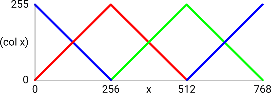
(defun col (x)
(let ((y (mod x 768)))
(max (if (< y 256) y (- 511 y)) 0)))
The function col varies the level of the red component of a NeoPixel in a triangle wave for values of x from 0 to 512. The green and blue components are offset by 256 and 512 respectively, and the value of x is taken mod 768, so the levels of the three components vary out of phase:
To run the pattern call:
(wave len speed)
where len is the length of the NeoPixel strip, and speed is the rate at which the colours change; values between 1 (slow) and 20 (fast) give good results.
- ^ NeoPixel Überguide on Adafruit.
- ^ NeoPixel Diffused 8mm Through-Hole LED on Adafruit.
- ^ NeoPixel Diffused 5mm Through-Hole LED on Adafruit.
- ^ NeoPixel RGB 5050 LED on Adafruit.
- ^ Mini 3535 RGB LEDs on Adafruit.
- ^ NeoPixel Nano 2427 RGB LEDs on Adafruit.
- ^ NeoPixel Addressible 1515 LEDs on Adafruit.
- ^ WS2812 datasheet on Adafruit.
- ^ Understanding the WS2812 on cpldcpu.com.