Adafruit nRF52840 boards
The Adafruit CLUE and Adafruit ItsyBitsy nRF52840 are each based on the Nordic Semiconductor nRF52840 ARM Cortex-M4 microcontroller running at 64 MHz, and with 1 Mbyte of flash program memory and 256 Kbytes of RAM. They also include 2 Mbytes of DataFlash that uLisp uses to allow you to save and reload the Lisp image.
Install the ARM version of uLisp for use with these boards.
Update
21st March 2023: The problem with the serial interface on these boards is fixed in uLisp Release 4.4, and the graphics extensions are now supported on the Adafruit Clue; see Graphics extensions.
Boards
Adafruit CLUE
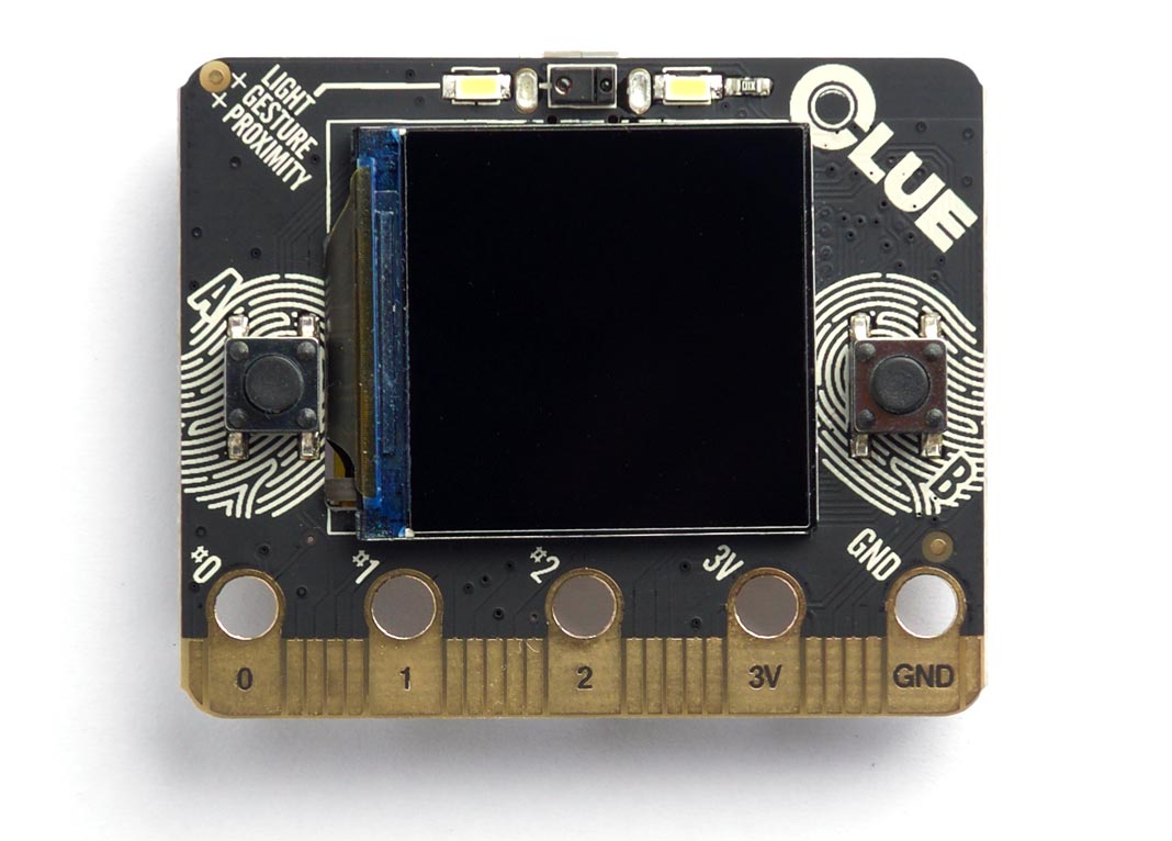
The CLUE board from Adafruit [1] is a great choice if you want a fast platform for running uLisp, with a selection of sensors already fitted on the board. It matches the form factor of the popular BBC Micro Bit:
Installing uLisp on the Adafruit CLUE
You can install the ARM version of uLisp on an Adafruit CLUE using the Arduino IDE as follows:
- Download the ARM version of uLisp from the downloads page: Download and install uLisp.
- Open the Boards Manager… from the Board item on the Tools menu, search for nRF52, and install Adafruit nRF52 Boards.
- Connect the Adafruit CLUE to your computer using a USB cable.
- Select Adafruit CLUE from the Adafruit nRF52 Boards section on the Board menu.
Upload uLisp
- Download the latest ARM version of uLisp from the Download uLisp page.
- To use the graphics extensions uncomment the compile option:
#define gfxsupport
- Select the board's USB port from the Port menu.
- Upload uLisp to the board.
Using uLisp
- You may need to select the board's USB port from the Port menu again.
- Select Serial Monitor from the Tools menu.
- Enter Lisp commands.
Pin connections
The Adafruit CLUE provides a BBC Micro Bit style edge connector. For a pinout see Adafruit CLUE Pinout.
The board also includes two pushbuttons, a 1.3" 240x240 colour TFT display, and several sensors. See Example programs below for examples of using these from uLisp.
Buttons
Like the BBC Micro Bit the front of the Adafruit CLUE provides two pushbuttons on pins 5 (left) and 11 (right). You can read these with the following program:
(defun buttons ()
  (pinmode 5 2)
  (pinmode 11 2)
  (loop
   (print
    (list (digitalread 5) (digitalread 11)))
   (delay 1000)))
The pinmode option should be set to 2 for input pullups. Run it by typing:
(buttons)
Digital inputs and outputs
The Adafruit CLUE provides 21 digital inputs/outputs, on pin numbers 0 to 20.
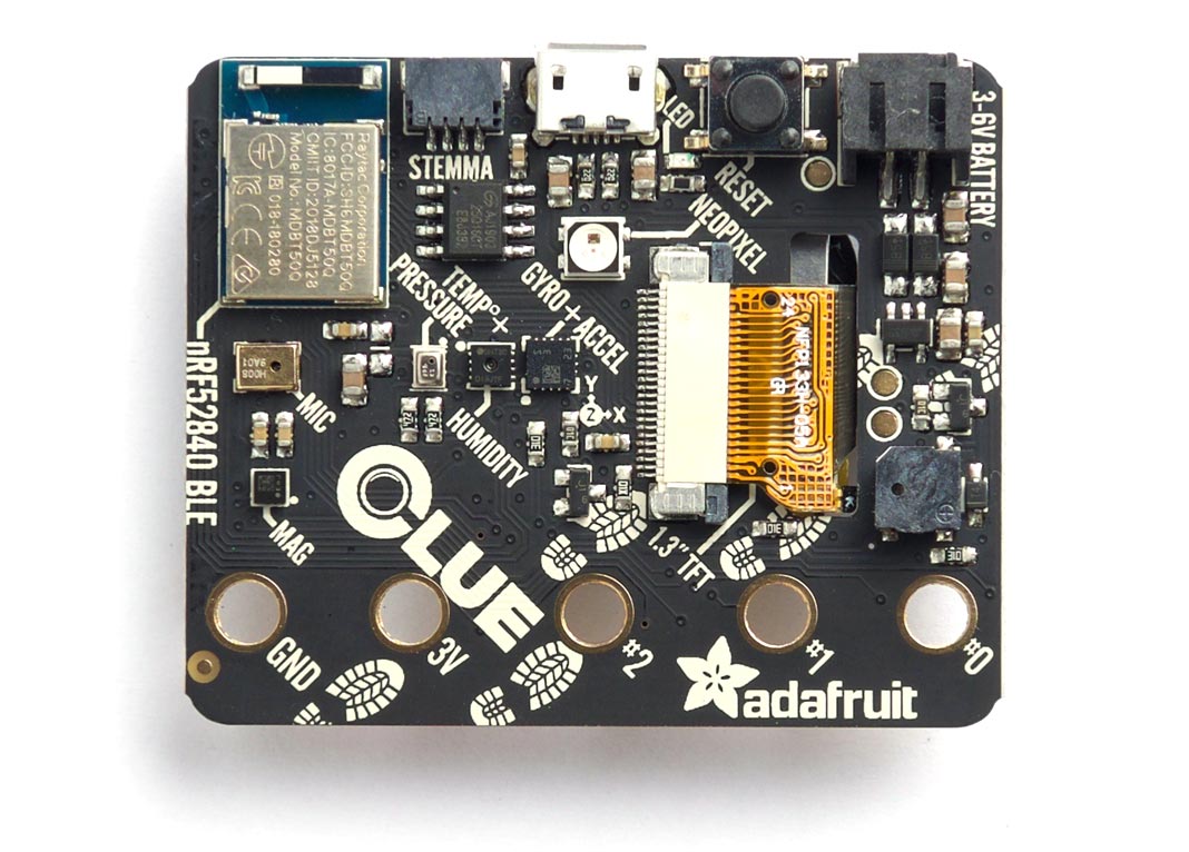
LED
The reverse of the Adafruit CLUE has a red LED on pin 17. You can flash it with the following program:
(defun blink (&optional x)
  (pinmode 17 t)
  (digitalwrite 17 x)
  (delay 1000)
  (blink (not x)))
Run it by typing:
(blink)
Exit from the program by entering ~.
Analogue outputs
Any pin can also be used as an 8-bit PWM analogue output.
For example, you can pulsate the red LED slowly on and off with the program:
(defun pulse ()
  (let (down)
    (loop
     (dotimes (x 256)
       (delay 5)
       (analogwrite 17 (if down (- 255 x) x)))
     (setq down (not down)))))
Run it by typing:
(pulse)
Exit from the program by entering ~.
White LEDs
The white LEDs are on pin 43; you can control them with:
(defun white-leds (on)
  (pinmode 43 t)
  (digitalwrite 43 on))
Analogue inputs
There are eight analogue inputs on pin 0, 1, 2, 3, 4, 10, 12, and 16.
Speaker
The Adafruit CLUE includes a buzzer on pin 46 that can be used to play tunes. For example, the following function scale plays the scale of C on pin 3:
(defun scale ()
  (mapc
   (lambda (n) (note 46 n 4) (delay 500))
   '(0 2 4 5 7 9 11 12))
  (note))
To run it, enter:
(scale)
I2C devices
You can run the following port scanner to see all the devices on the CLUE's I2C bus:
(defun scn ()
  (dotimes (p 127)
    (with-i2c (str p)
      (when str (print p)))))
The following table gives details of the I2C devices:
| Address | Device |
| 28 or #x1c | LIS3MDL Magnetometer |
| 57 or #x39 | APDS9960 Proximity, Light, and Gesture Sensor |
| 68 or #44 | SHT30-D Humidity Sensor |
| 106 or #x6a | LSM6DS33 Accelerometer and Gyroscope |
| 119 or #x77 | BMP280 Pressure Sensor |
BMP280 temperature and pressure sensor
The BMP280 provides temperature and pressure readings. For interface details see BMP280 Pressure Sensor.
SHT30-D Humidity Sensor
The SHT30-D provides temperature and humidity readings. For interface details see SHT30-D and SHT31-D Humidity Sensors.
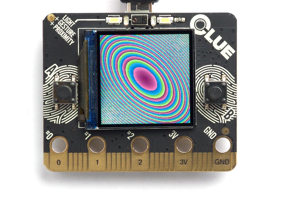
TFT 240x240 Colour Graphics Display
The Adafruit CLUE incorporates a 1.3" TFT 240x240 colour graphics display based on the ST7789 driver. It's connected to the SPI1 port, so you can write to it from uLisp using with-spi.
For a simple graphics demo showing how to plot points in colour on the display see Adafruit CLUE plotting demo:
Adafruit ItsyBitsy nRF52840
The Adafruit ItsyBitsy nRF52840 [2] is the same size as Adafruit's other ItsyBitsy boards.
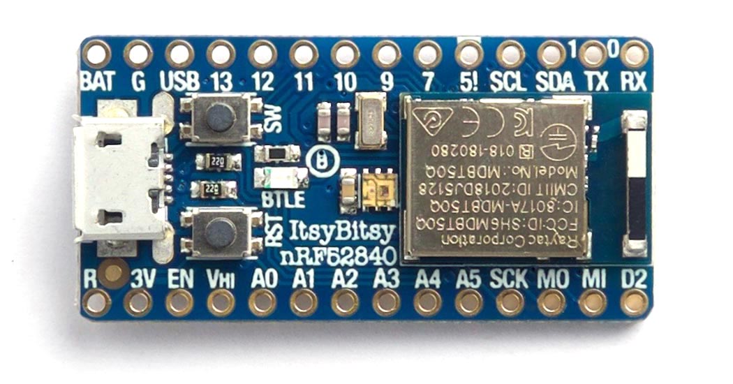
LEDs
The Adafruit ItsyBitsy nRF52840 has a blue LED connected to the digital pin 3 which you can flash with the following program:
(defun blink (&optional x)
  (pinmode 3 t)
  (digitalwrite 3 x)
  (delay 1000)
  (blink (not x)))
Run it by typing:
(blink)
All pins can also be used as analogue pins, so you can pulsate the blue LED slowly on and off with the program:
(defun pulse ()
  (let (down)
    (loop
     (dotimes (x 256)
       (delay 5)
       (analogwrite 3 (if down (- 255 x) x)))
     (setq down (not down)))))
Run it by typing:
(pulse)
Exit from either program by entering ~.
DotStar RGB LED
The Adafruit ItsyBitsy nRF52840 has a DotStar (APA102) RGB LED mounted on the board. For more information about DotStar LEDs see Driving DotStar RGB LEDs.
Here's a program to set the LED to an arbitrary colour and brightness:
First we define variables for the clock and data pins; these are connected to Arduino pins 6 (clock) and 8 (data):
(defvar clk 6)
(defvar data 8)
Here's a routine to send a byte to the display, MSB first, toggling the clock pin after each bit:
(defun send (byte)
  (dotimes (i 8)
    (digitalwrite clk 0)
    (digitalwrite data (logand (ash byte (- i 7)) 1))
    (digitalwrite clk 1)))
Finally here's the function to send the appropriate stream of bits to the LED to define its colour and brightness:
(defun dotstar (bri blue green red)
  (pinmode clk t)
  (pinmode data t)
  (mapc send (list 0 0 0 0 (logior bri #xe0) blue green red #xff)))
To set the LED evaluate:
(dotstar bri blue green red)
where bri is the brightness (from 0 to 31), and blue, green, and red are the colour components, from 0 to 255. For example, this sets the LED to magenta (blue+red) at low brightness:
(dotstar 1 255 0 255)
Button
The ItsyBitsy nRF52840 has a button connected to digital input 4. You can read it with the following program:
(defun button ()
  (pinmode 4 2)
  (loop
   (print (digitalread 4))
   (delay 1000)))
The pinmode option is set to 2 for an input pullup. Run it by typing:
(button)
Analogue inputs
The ItsyBitsy nRF52840 provides seven analogue inputs on pins 14 to 20.
- ^ Adafruit CLUE - nRF52480 Express on Adafruit.
- ^ Adafruit ItsyBitsy nRF52840 Express on Adafruit.